
This post is a continuation from Part 1 on How Do You Install Electrical Molding. Lately, we have gone through the choice of material.
We will now cover:
Step 1: Prepare for installation
Step 2: Make the cuts
Step 3: Attach the electrical moldings
Step 4: Place the pedestals
Step 5: Pull the cables
Step 6: Connect the devices
Step 7: Make the finishes
Step 1. Prepare for installation
– Start at the right place
If you are installing a new power line:
– Perform the installation from the switchboard.
– Protect it with a circuit breaker of:
– 16 A if it is a lighting circuit or sockets wired in 1.5 mm²;
– 20 A in 2.5 mm².
In the case of an extension: transpose your installation to a junction box.
Good to know: it is possible to start again from a socket to complete the same circuit, as long as the regulatory number of connection points is not exceeded: five for 1.5 mm2 wirings, eight for 2.5 mm2 wirings.
Establish the route
Your electrical moldings can run vertically, horizontally (walls and ceiling), but never at an angle. Make sure they are as discreet as possible.
Locate branches, switches, and outlets
According to the NF C 15-100 standard, switches should be placed at a height of between 80 and 130 cm.
For conventional 16 or 20 A sockets, the axis of the cells (holes) must be at least 5 cm from the finished ground level.
– Draw the location of the moldings that will house your cables.
Caution: before working on your electrical installation, turn off the power!
Step 2. Make the cuts
– Measure the lengths of the molding or baseboard to be installed.
– Leave the covers in place to make the necessary cuts.
– Make the cut with a backsaw, preferably in a miter box, or with a framing saw.
– Make the corner joints either directly at 45° or with straight cuts and with suitable fittings, either inward or outward. Connections are also provided for butt joints.
– Take the precaution of deburring the cuts with a soft file or cutter and remove dust.
Step 3. Attach the electrical moldings
Adhesive bonding is the simplest and fastest method on a smooth surface.
– Degrease the PVC, with methylated spirits for example, before gluing it.
– After unclipping the cover, apply a bead of adhesive sealant in a zigzag pattern to the reverse side of the molding using the cartridge gun.
– Apply the molding to the wall and press down firmly for the time indicated on the glue sealant cartridge, usually 20 to 30 seconds.
– If necessary, reinforce the nail fastening at different points.
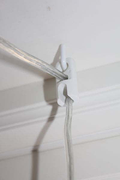
– Take advantage of this opportunity to place clips to hold the electrical wires at the same time.
Note: Use nails that are suitable for the material: made of hardened steel for concrete, twisted for a better hold in soft materials such as plaster.
Step 4. Place the base plates
– Clip the switch and outlet sockets to the desired locations.
– Use a pencil to mark the fixing points through the holes in the bottom.
– Remove the base to drill and anchor the wall.
– Replace the base and screw it in place.
Step 5. Pull the cables
– Strip the ends of the conductors using the stripping pliers and connect them to your starting point: switchboard circuit breaker or junction box.
– Use the correct wire cross-sections (or conductors) and observe the standard colors: phase in red or black, neutral in blue, earth in yellow/green stripes.
The wiring into a junction box can be done with dominoes or quick-connect strips.
Tip: if you are making several circuits (lighting, sockets, etc.), mark them by wrapping the corresponding wires with adhesive tapes of different colors.
Then unroll your wiring by holding it with clips every 30 to 40 cm.
Depending on the size of your installation and the model of molding, run the wires in the same compartment or unbundle them.
Do not hesitate to multiply the clips to keep the wires inside the moldings. If they stick out a little bit everywhere, you will have trouble making changes in direction (outgoing or incoming angles, branches) and clipping the covers.
Good to know: the NF C 15-100 standard recommends separating high currents (230 V power supply circuits) from low currents (low-voltage lighting, computers, telephone, TV…). They can run in the same molding but in separate compartments.
Step 6. Connect the devices
Before you make your connections, you should know that:
– Power outlets are powered by three conductors: neutral, phase, and ground.
– Purple wire is commonly used for the shuttle, which is easy to distinguish from the others.
– Switches do not connect to the ground. The number of wires required depends on the type of connection: two for single lighting, three for a shuttle, etc.
To make your connections:
– Strip the ends of the conductors using the stripping pliers, over a length of 5 to 6 mm.
– Connect the mechanisms of the devices by screwing the wires into the corresponding terminals with the screwdriver:
Often L (line) for phase, N for neutral.
The ground wire of the sockets is connected to a central terminal marked with an international symbol.
On modern switches, the terminals reserved for the shuttles are generally identified by the numbers 1 and 2.
Step 7. Make the finishes
– Check that your connections are secure.
– Finish assembling the equipment: covers, plugs, switches.
– On the switches, the knob last fits on the mechanism.
– On sockets, by convention, the ground pin of the sockets is placed over the holes (but if you do the opposite, it will still work).
Note: To ensure a perfect joint, the molding covers should be retracted about 10 mm under the switch and socket covers.
Thank you for staying posted on our new blog posts. Hope these two posts (Part 1 & 2) would be of any help to you. Remember to leave your comments below and share these posts with your friends.