
Refrigeration Link: Explanation, Composition, Applications
Contents
The principle of a refrigeration link
Characteristics of a refrigeration line
A refrigeration line in refrigeration and air conditioning is a pipe through which a heat transfer fluid circulates and is intended to be cooled or refreshed. The role of the refrigeration line is to ensure the transport of this fluid without loss of quantity by leakage or evaporation and loss or addition of calories to preserve its temperature (and, in this case, its cold). A refrigeration link is required when the device intended to produce the cold is moved away from the diffuser, which allows it to be distributed.
This refrigeration link exists on most of our refrigerators, cold rooms, and air conditioners.
The principle of a refrigeration link
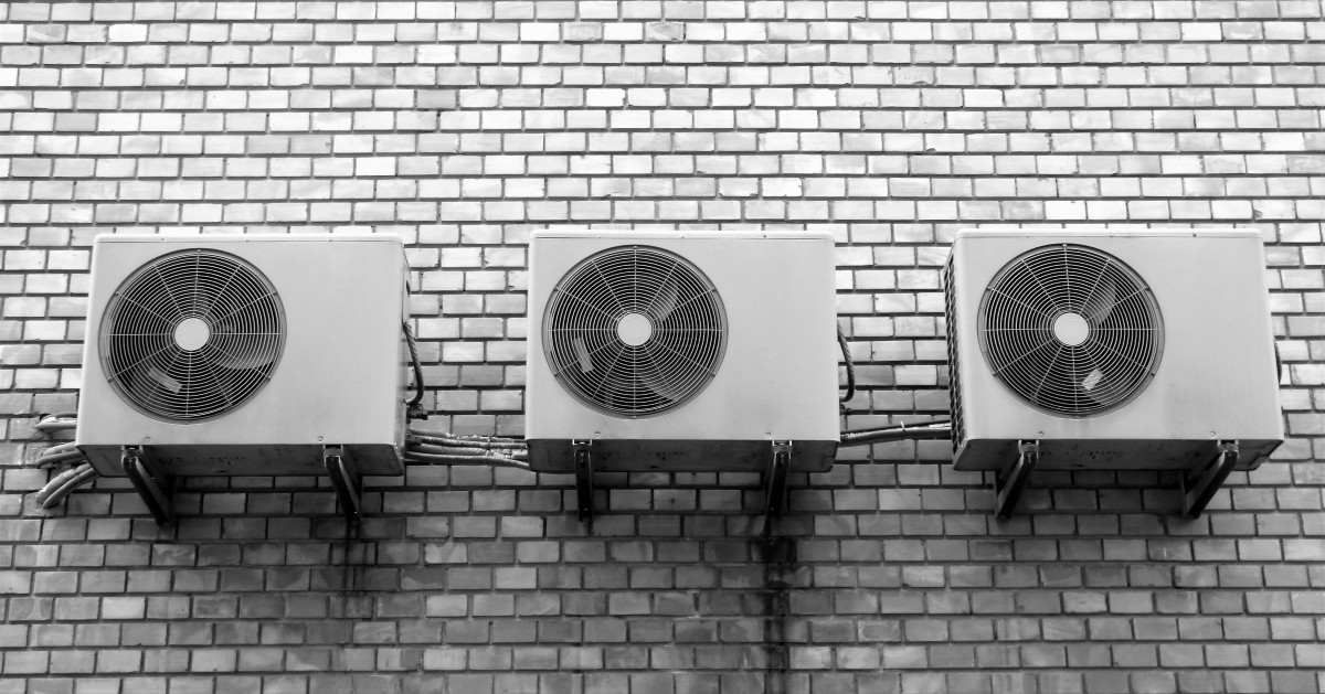
A refrigeration link is composed (especially in air conditioning) of two tubes to create a circuit in which the refrigerant circulates between the external unit (compressor or air conditioning group) and the diffuser(s) (in split(s) or console(s) or in ductable).
The problem of refrigerant transport is twofold. On the one hand, refrigerants (HFC, HCFC, ammonia, propane, and isobutane) are highly volatile, and on the other hand, any cold in a warmer environment dissipates quickly by generating condensation.
The role of the refrigeration link is, therefore, threefold
to ensure the leakage-free transport of a particularly volatile fluid (capable of passing through thin and not very thick walls);
to limit the loss of calories so that the refrigerant keeps its low temperature as long as possible;
to resist condensation produced during the temperature exchange inherent to the journey in a hotter environment and, if possible, to limit the formation of condensation.
Characteristics of a refrigerant line
Composition of a refrigerant line
To accomplish these tasks, the refrigeration link, especially in air conditioning, consists of the following:
A return circuit composed of two tubes to exchange the refrigerant from and to the cold production unit (outdoor unit) and the cold diffusion units (splits, consoles);
copper tubes because of the mechanical properties of this material and of sufficient thickness to limit the losses in calories and volume;
thermal insulation to limit heat loss, resistance to the formation, and effects of condensation.
Good to know: it is possible to create a refrigeration link circuit by using two separate tubes (one outward and one return) or by using a bi-tube link where the two tubes are joined together like an electrical cord (one cord but composed of a + wire and a – wire).
Section and thickness of copper tubes
Depending on the power of the cooling unit and the length of the refrigeration link to be created (distance, multiplication of diffusers), copper tubes of varying cross-section and metal thickness are used:
The section is expressed in inches and fractions of an inch: ¼, 3/8, ½, 7/8, etc.
Copper thickness is expressed in millimeters: 0.8 mm, 1 mm, and 1.2 mm.
You can install rigid copper rods or flexible copper coils, bare or already coated with thermal insulation (insulated refrigeration link).
Good to know: the diameter of the flow pipe and the return pipe differs, which is why a double refrigeration connection is composed of two pipes joined together but with different cross sections. To dimension the connection, it is necessary to respect the manufacturer’s indications of the air conditioner.
Insulating a refrigerant line
When the refrigeration link is insulated, the thermal and mechanical insulation resistant to condensation is generally ensured by a layer of high-resistance polyethylene foam in contact with the copper and an external layer of embossed polyethylene foam in contact with the walls to be crossed. The thickness of each layer of insulation is also expressed in millimeters.
Example: a double insulated refrigeration link 1/4-5/8 thickness copper insulation 0.8×1.9x10mm means: diameter of the copper tube N° 1: ¼ (6.3 mm) – diameter of the copper tube N° 2: 5/8 (15.9 mm) – wall thickness of the copper tubes 0.8 mm – thickness of the high resistance insulation 1.9 mm – thickness of the embossed insulation 10 mm.
Depending on your skills, your tools, and the network to be created, you can then opt for bare or insulated, rigid or flexible tubes of the desired length and possibly already equipped with fittings (“pre-ducted” tubes) or even already charged with refrigerant gas with a safety valve that does not require either a vacuum or a refrigerant pre-charge.
Good to know: the fire resistance class of the insulation surrounding the copper of the refrigerant connection is usually also specified. Except for specific installations, the required class is M1 – combustible but non-flammable materials.